
|
BRHS /
Two Phase JetsThe phenomena associated with two phase jet dispersion are reviewed by Bricard and Friedel (BricardP:1998). Within a short distance just downstream from the outlet, the flow can experience drastic changes which must be considered for subsequent dispersion calculations. The physical phenomena taking place in this region comprise (i) flashing if the liquid is sufficiently superheated, (ii) gas expansion when the flow is choked and (iii) liquid fragmentation. The corresponding quantities to be determined as initial conditions for subsequent dispersion calculations are the flash fraction, the jet mean temperature, velocity and diameter, and the droplet size. 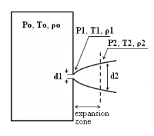 Fig. 1: Model of a two-phase flashing jet Flashing occurs when the liquid is sufficiently superheated at the outlet with respect to atmospheric conditions and corresponds to the violent boiling of the jet. The vapour mass fraction after flashing is most often determined in the models by assuming isenthalpic depressurization of the mixture between the outlet (position 1 in Fig. 1) and the plane downstream over which thermodynamic equilibrium at ambient pressure is attained (position 2 in Fig. 1):
Where Hfg is the latent heat of vaporization and Cpf is the liquid specific heat. When the flow is choked at the outlet, the gas phase expands to ambient pressure within a downstream distance of about two orifice diameters. This causes a strong acceleration of the two-phase mixture and usually an increase of the jet diameter. In the models, the velocity and diameter of the jet at the end of the expansion zone are given by the momentum and mass balance, respectively, integrated over a control volume extending from the outlet (position 1) to the plane where atmospheric pressure is first reached (position 2). It is assumed that no air is entrained in this region. The approach is similar to the one described above for choked gaseous hydrogen jets. The corresponding equations according to Fauske and Epstein (FauskeHK:1988) are:
Liquid fragmentation (or atomization) is caused by two main physical mechanisms: flashing and aerodynamic atomization. With flashing atomization, the fragmentation results from the violent boiling and bursting of bubbles in the superheated liquid, whereas aerodynamic atomization is the result of instabilities at the liquid surface. The determination of the initial droplet size (position 2) is a required initial condition, if the subsequent dispersion models account for fluiddynamic and thermodynamic non-equilibrium phenomena, like rainout and/or droplet evaporation. In the case of aerodynamic fragmentation, the maximum stable drop size is usually given by a critical Weber number, which represents the ratio of inertia over surface tension forces:
Where σ is the surface tension of the liquid, ρg is the gas density, dmax is maximum stable droplet diameter and ΔU the mean relative velocity between both phases. A range of values are used for the maximum Weber number, see (BricardP:1998) with 12 being the most common value. In the previous discussion the mass flow rate and outlet conditions (position 1) were assumed known. Hanna and Strimaitis (1989)(HannaSR:1989) have reviewed various approaches for calculating the release mass flow rate for liquid and two-phase flow releases. Detailed information on the subject can be found in chapter 15 of Lees (LeesFP:1996a) , in chapter 9 of Etchells and Wilday (EtchellsJ:1998) as well as in the older review of critical two phase flow models by D’Auria and Vigni (DAuriaF:1980) If the liquid in the reservoir is at saturated conditions, and if equilibrium flow conditions are established (i.e. for outflow pipe lengths > 0.1 m) then the two-phase choked mass flux (kg s-1 m-2) can be calculated following Fauske and Epstein (FauskeHK:1988):
Where Hfg is the latent heat of vaporization, Cpf is the liquid specific heat, T is the saturation temperature which is function of the storage pressure p, vg, vf are the saturated vapour and liquid specific volumes. This equation applies only if the vapor mass fraction after depressurization to atmospheric pressure (position 2) obeys the following criterion:
Figure 2 shows the equilibrium choked mass flux calculated using Eq. (4) for an LH2 release as function of the storage pressure. 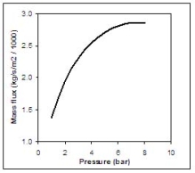 Fig. 2: Mass flux calculated using Eq. (4) for an LH2 release, as function of the storage pressure ReferencesInvalid BibTex Entry! |